Thank you for your interest in ros2_control. This repository was developed with the purpose of supporting the workshop on ros2_control @ ROSCon2022 in Kyoto, Japan. Whether you participated or not, the repository will provide you with detailed instructions on how to use the ros2_control framework and explain functionality and purpose of its individual parts.
After cloning the repository, go to your source workspace and execute the following commands to import the necessary repositories and to install all dependencies:
vcs import --input roscon2022_workshop/roscon2022_workshop.repos .
rosdep update
rosdep install -y -i --from-paths .
In short, ros2_control is a control framework for ROS2. But actually, it is much more, it is the kernel of the ROS2 system that controls robots:
- it abstracts hardware and low-level control for other frameworks such as MoveIt2 and Nav2;
- it provides resource access management,
- controls their lifecycle and so on.
For more details check this presentation
The structure of the repository follows the flow of integrating robots with ROS2 and these are the following steps:
-
📑 Setting up the hardware description for ros2_control
- 🗒 Setting up the robot's URDF using XACRO
- 📝 Extending the robot's URDF with the
<ros2_control>tag
-
🖥 Using the Mock Hardware plugin for easy and generic testing of the setup (and how it can save you ton of time and nerves)
- 🛠 How to setup Mock Hardware for a robot?
- 🔩 How to test it with an off-the-shelf controller?
-
⚙ Getting to know the roles of the main components of the ros2_control framework: Controller Manager, Controllers, Resource Manager and Hardware Interface
-
🔬 Introspection of the ros2_control system
------------------- lunch ---------------------
-
💻 Simulating your hardware using the Gazebo Classic and Gazebo -- 30 min
-
🔃 Become familiar with the lifecycle of controllers and hardware. Learn how to use them.
-
🤖 How to write a hardware interface for a robot
-
🛂 How to write a controller
-
🔗 Reusing a standard controller and creating controller-chains
-
♻ Modular reuse of hardware drivers for complex systems
-
🤖🤖🤖 Managing multiple robots with ros2_control
-
👑 Dr. Denis' Tips:
- 💉 Parameter injection
- ⚖ Typical setup of robots and their packages
- learn how to setup the URDF of a robot using XACRO macros
- learn what URDF changes are needed to integrate a robot with
ros2_control
For any robot that is used with ROS/ROS2 an URDF description is needed. This description holds information about kinematics, visualization (e.g., for Rviz2) and collision data. This description is also used by popular ROS2 high-level libraries like, MoveIt2, Nav2 and Simulators.
In this excercise we will focus on setting up the description using the XACRO format which is highly configurable and parameterizable and generally better to use than the static URDF format.
Branch: 1-robot-description/task
Task is to setup the XACRO for RRbot in a package called controlko_description.
Kinematics:
- 2 DoF
- 1st joint is on a pedestal (box 30x30x30 cm) 30 cm above the ground and rotates around the axis orthogonal to the ground
- 1st link is 50cm long (cylinder with 20cm diameter)
- 2nd joint is rotation orthogonal to the first link's height
- 2nd link is 60cm long (10x10cm cross-section 5x5cm)
Hardware:
- Force Torque Sensor at TCP (6D)
- 2 digital inputs and output (outputs can be measured)
References:
Files to create or adjust:
rrbot_macro.xacro- macro with kinematics and geometries for therrbotrrbot.urdf.xacro- main xacro file for the robot where macro is instantiatedview_robot.launch.py- loading and showing robot inrviz2
TIPP: RosTeamWS tool has some scripts that can help you to solve this task faster (on the branch is this already implemented). Resources:
Branch: 1-robot-description/solution
Check the files listed above and execute:
ros2 launch controlko_description view_rrbot.launch.py
to view the robot and move its joints using the Joint State Publisher GUI.
- learn what is Mock Hardware and how to use it
- learn how you can fast and easily test you controller's setup and parameters before you deal with simulation or real hardware
Mock Hardware is mocking ros2_control Hardware Interface based on the robot's description from the ros2_control tag.
Its purpose is to simplify and boost the development process when creating a new controller or setting up their configuration.
The advantage of using it, over simulation or real hardware, is a very fast start-up and lean functionality.
It is a well tested module helping you focus on other components in your setup knowing that your "hardware" behaves ideally.
NOTE: the functionality of Mock Hardware is intentionally limited and it only enables you to reflect commanded values on the state interfaces with the same name. Nevertheless, this is sufficient for most tasks.
TIPP:
- Dr. Denis recommends you to always start to develop things first with the Mock Hardware and then start switching to simulation or real hardware. This way you save time dealing with a broken setup with simulation or hardware in the loop.
-
Add
hardwaretag under theros2_controltag with pluginmock_components/GenericSystemand setmock_sensor_commandsparameter. The parameter create fake command interface for sensor values than enables you to simulate the values on the sensor. -
Create a launch file named
rrbot.launch.pythat starts the ros2_control node with the correct robot description.
NOTE: Currently, there is only GenericSystem mock component, which can mock also sensor or actuator components (because they just have a reduced feature set compared to a system).
- Setup the following controllers for the
RRBot:
Joint State Broadcaster- always needed to get/joint_statestopic from a hardware.Forward Command Controller- sending position commands for the joints.Joint Trajectory Controller- interpolating trajectory between the position commands for the joint.
-
Add to launch file spawning (loading and activating) of controllers.
-
Test forward command controller by sending a reference to it using
ros2 topic pubcommand. -
Create a launch file that starts
ros2_controllers_test_nodes/publisher_joint_trajectory_controllerto publish goals for the JTC.
TIPP: RosTeamWS tool has some scripts that can help you to solve this task faster. Resources:
Branch: 2-robot-mock-hardware
Check the files listed above and execute:
ros2 launch controlko_bringup rrbot.launch.py
then publish a command to the forward command controller:
ros2 topic pub /forward_position_controller/commands std_msgs/msg/Float64MultiArray "
layout:
 dim: []
 data_offset: 0
data:
 - 0.7
 - 0.7"
To start RRBot with JTC execute:
ros2 launch controlko_bringup rrbot.launch.py robot_controller:=joint_trajectory_controller
and open a new terminal and execute:
ros2 launch controlko_bringup test_joint_trajectory_controller.launch.py
NOTE: delay between spawning controllers is usually not necessary, but useful when starting a complex setup. Adjust this specifically for the specific use-case.
Start the previous example one more time and try to answer the following questions:
- What and where is Controller Manager?
- What are Controllers? How they can be seen in ROS2?
- What is Resource Manager? Where can you see it? How to access it?
- What is Hardware Interface? Where is this stored? How to interact with it?
TODO: Add diagram/figure here.
There are two options to interact with the ros2_control, first, using the CLI interface with commands like ros2 control <command> (package ros2controlcli), and second, using services from the controller manager directly.
Try to figure out how to answer the following questions using those tools:
- What controllers are loaded in the system?
- What is the state of the controllers?
- What hardware interfaces are there and in which state?
- Which interfaces are available?
- How can we switch between
forward_position_controllerandjoint_trajectory_controller? - What happens when you try to run all controllers in parallel?
- What interfaces are controllers using?
Also there are few graphical tools available for ros2_control: rqt_controller_manager and rqt_joint_trajectory_controller. Try to use those tools.
Answers to the questions:
ros2 control list_controllersros2 control list_controllersros2 service call /controller_manager/list_hardware_components controller_manager_msgs/srv/ListHardwareComponents {}ros2 control list_hardware_interfacesros2 run controller_manager spawner forward_position_controller --inactiveros2 control switch_controllers --deactivate joint_trajectory_controller --activate forward_position_controller- See output in the terminal where
ros2_control_nodeis running:ros2 control switch_controllers --activate joint_trajectory_controller ros2 control list_controllers -v
ros2_control is integrated with simulators using simulator-specific plugins.
Those plugins extend controller manager with simulator-related functionalities and enables loading hardware interfaces that are created specifically for the simulator.
Simulators are using description under <ros2_control> to setup the interfaces.
They are searched for interfaces with standard names, position, velocity and effort, to wire them with the internal simulator-states.
The plugins and interfaces for the simulators are the following:
Gazebo Classic
- Package:
gazebo_ros2_control - Simulator plugin:
libgazebo_ros2_control.so - HW interface plugin:
gazebo_ros2_control/GazeboSystem
Gazebo
- Package:
gz_ros2_control - Simulator plugin:
libign_ros2_control-system.so - HW interface plugin:
ign_ros2_control/IgnitionSystemNOTEignwill be switched togzvery soon!
Let's define those plugins for RRBot:
- Extend
rrbot.urdf.xacrowith<gazebo>tags defining simulator plugins and parameters. - Add hardware interface plugins under
<ros2_control>tag in the filerrbot_macro.ros2_control.xacro. - Add new launch file
rrbot_sim_gazebo_class.launch.pyfor starting Gazebo Classic simulation. - Add new launch file
rrobt_sim_gazebo.launch.pyfor starting Gazebo simulation.
Branch: 5-simulation
Check updated files from the above list. To start the Gazebo Classic simulation use:
ros2 launch controlko_bringup rrbot_sim_gazebo_classic.launch.py
To start the Gazebo simulation use:
ros2 launch controlko_bringup rrbot_sim_gazebo.launch.py
Now execute the test script for joint trajectory controller to move the robot.
ros2 launch controlko_bringup test_joint_trajectory_controller.launch.py
NOTE: When running simulation be sure to set the joint limits defined in the macro file.
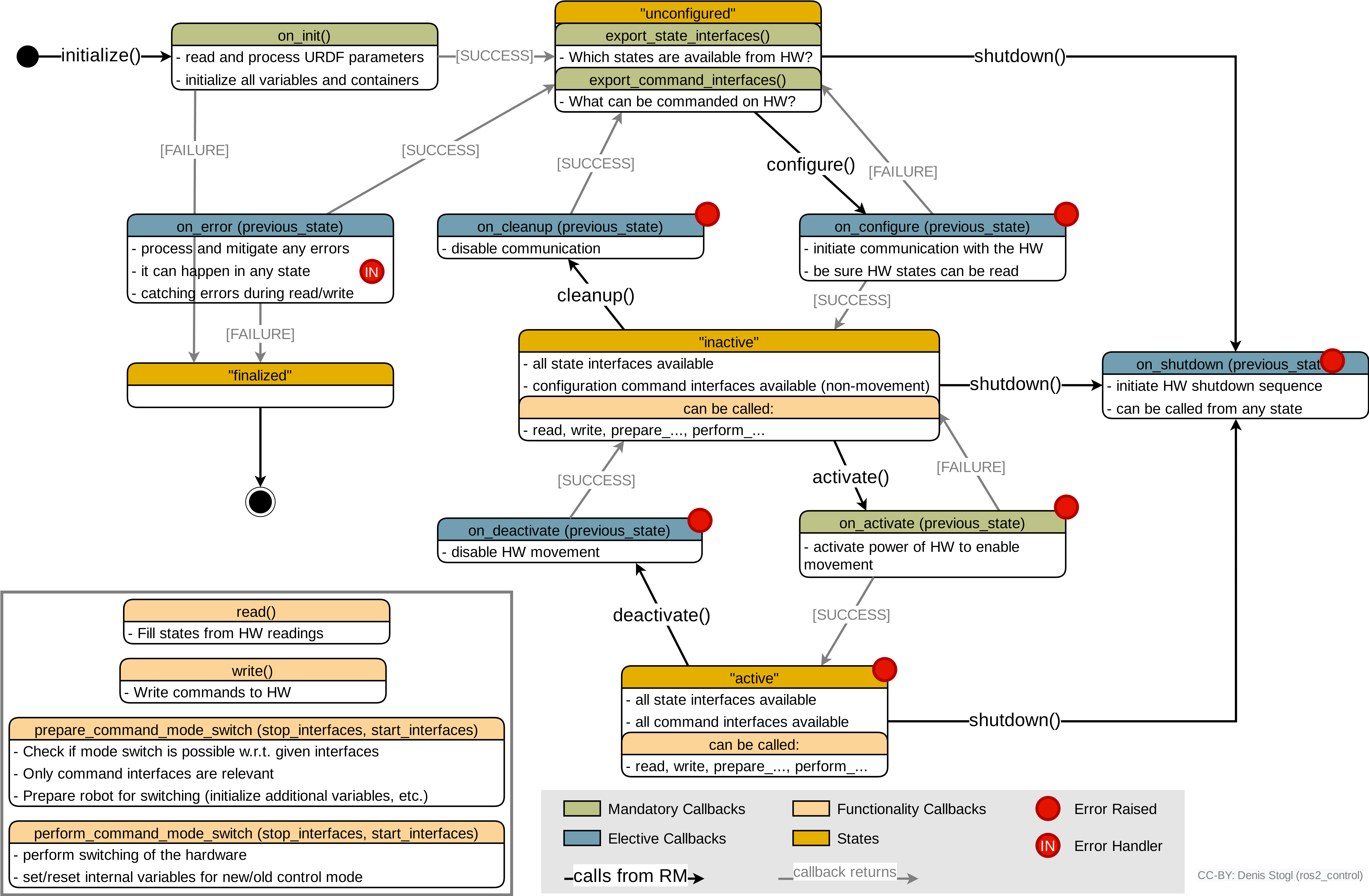
ros2_control enables you to control the lifecycle of controllers and hardware components.
The states and transitions are the same as for the Lifecycle Nodes.
Check the diagram below for more details:
- Start the
RRbotwithMock System - Check the lifecycle state of controllers and hardware interfaces
- Activate the
joint_trajectory_controllercontroller. What else do you have to do to achieve that? - Set hardware to
inactivestate. What is now the internal state of the ros2_control instance? - Have you heard of the
RQT Controller Managerplugin? Try it!
Branch: 6-getting-know-lifecycle
Execute the following commands to get the answers from the task:
-
ros2 launch controlko_bringup rrbot.launch.py -
Execute in another terminal:
ros2 control list_controllers ros2 service call /controller_manager/list_hardware_components controller_manager_msgs/srv/ListHardwareComponents {} -
Execute the following commands (this is one of multiple valid ways)
ros2 control load_controller joint_trajectory_controller ros2 control set_controller_state joint_trajectory_controller inactive ros2 control switch_controllers --deactivate forward_position_controller --activate joint_trajectory_controller -
Execute the following commands (this is one of multiple valid ways)
# stop controller
ros2 control switch_controllers --deactivate joint_trajectory_controller
# get component name
ros2 service call /controller_manager/list_hardware_components controller_manager_msgs/srv/ListHardwareComponents {}
# set component state
ros2 service call /controller_manager/set_hardware_component_state controller_manager_msgs/srv/SetHardwareComponentState "
name: rrbot
target_state:
 id: 0
 label: inactive"
# check internals of ros2_control
ros2 control list_controllers
ros2 control list_hardware_interfaces
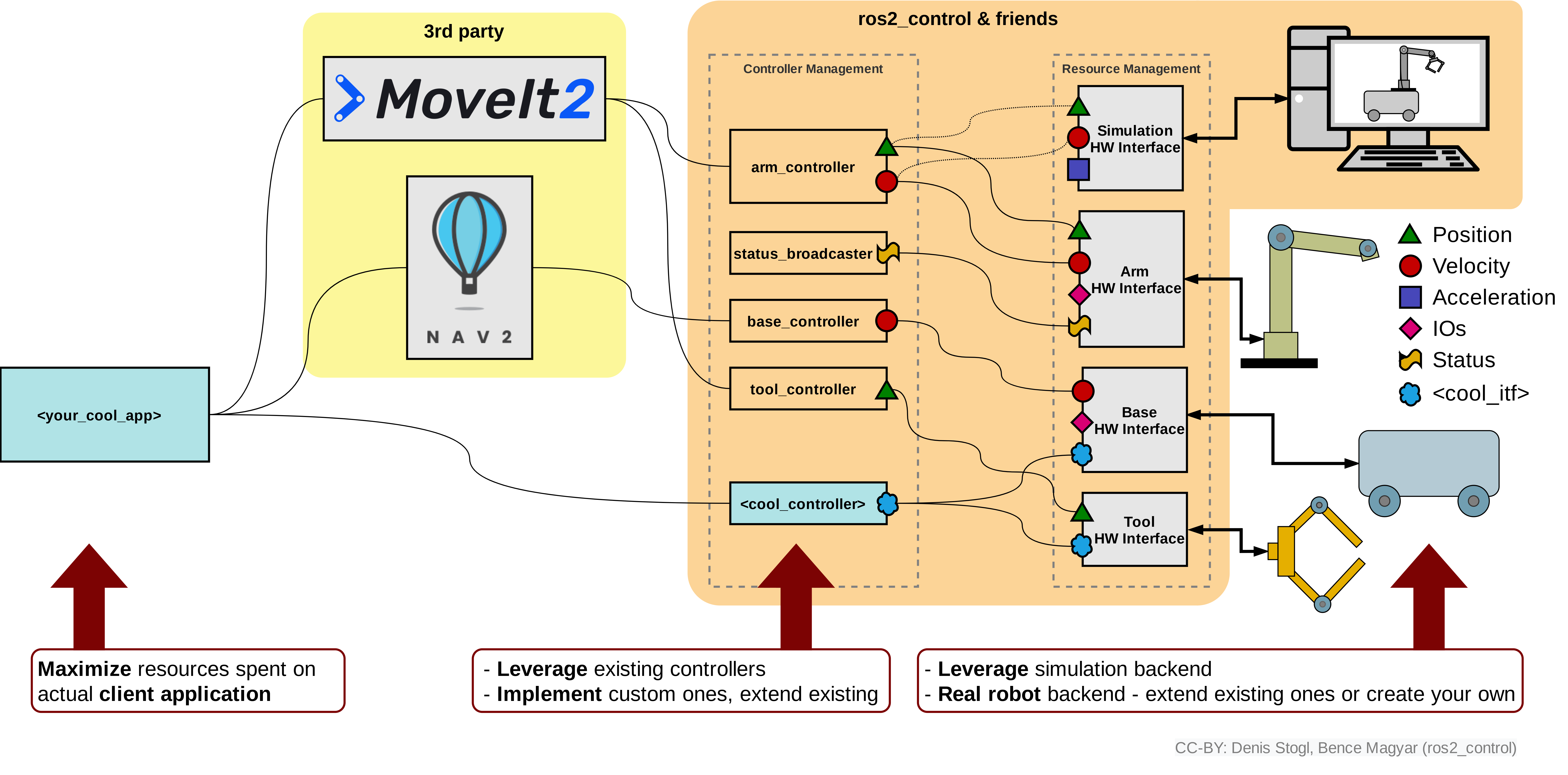
Hardware interface is the lowest layer towards hardware in ros2_control. A hardware interface is a driver for a specific robot that exports interfaces to the framework for controllers to use them. Overview of ros2_control shows this graphically:
Lifecycle diagrams from the Task 6 explains in detail when which method is used.
Branch: 7-robot-hardware-interface/task
Write a hardware interface for the RRBot.
-
Create or adjust a package named
controlko_hardware_interfacewith hardware interface files. -
Write a hardware interface that uses a header-only library for the communication with RRBot:
- check the file
controlko_hardware_interface/include/controlko_hardware_interface/dr_denis_rrbot_comms.hpp - use Writing a new hardware interface manual to implement everything needed.
- extend the URDF file to use hardware interface
- check the file
-
During the implementation of the hardware interface take care about the following details:
- Which control modes are supported?
- What happens if an incompatible controller is activated?
-
What are the capabilities?
TIPP: RosTeamWS tool has some scripts that can help you to solve this task faster. Resources:
Branch: 7-robot-hardware-interface/solution
Execute the following commands to get the answers from the task:
-
ros2 launch controlko_bringup rrbot.launch.py use_mock_hardware:=false -
Test execution with
forward_position_controllerandjoint_trajectory_controller -
Test activation of an incompatible controller using:
ros2 control load_controller incompatible_joint_trajectory_controller
ros2 control set_controller_state incompatible_joint_trajectory_controller inactive
ros2 control switch_controllers --deactivate forward_position_controller --activate incompatible_joint_trajectory_controller
Controllers in ros2_control are serving on the one hand as "interfaces" towards the ROS-world and on the other hand implement algorithms to control the hardware. A controller, when activated, gets loaned access to the exported hardware interface to read and write values directly from/to memory locations that the hardware interface is using. Although somewhat limited, this concept enables deterministic and reliable data flow between controllers and hardware interfaces (drivers).
Branch: 8-write-controller/task
Write a controller for RRBot robot that takes joint displacements as input and updates new joint positions for it.
-
Add controller files into the
controlko_controllerspackage. -
During the implementation take care about the following details:
-
How is data exchanged between the controller's callbacks and the
updatemethod? -
How are statuses from controller published to ROS topics?
-
Controller should have a slow mode where displacements are reduced to half.
-
Controller accepts a command only once.
-
-
Write a controller that uses
control_msgs/msg/JointJogmessage for the input.- Check the definition of
JointJogmessage - Alternatively use the CLI command:
ros2 interface show control_msgs/msg/JointJog - Use Writing a new controller manual to implement the controller
- Check the definition of
TIPP: RosTeamWS tool has some scripts that can help you solve this task faster. Resources:
- Creating a new package
- Setup controller package - choose setup of "normal" controller
Branch: 8-write-controller/solution
First check the code:
- ros2_control is now using PickNik's generate_parameter_library so simpler and cleaner parameters usage and definition.
- parameters are defined in [./src/displacement_controller.yaml] file
- example controller setup is in:
- [./test/displacement_controller_params.yaml] - when controller is used directly with the hardware
- [./test/displacement_controller_preceeding_params.yaml] - when controller is used at the beginning of the chain (see the next task for details!)
Execute the following commands to see the new controller running:
ros2 launch controlko_bringup rrbot.launch.py
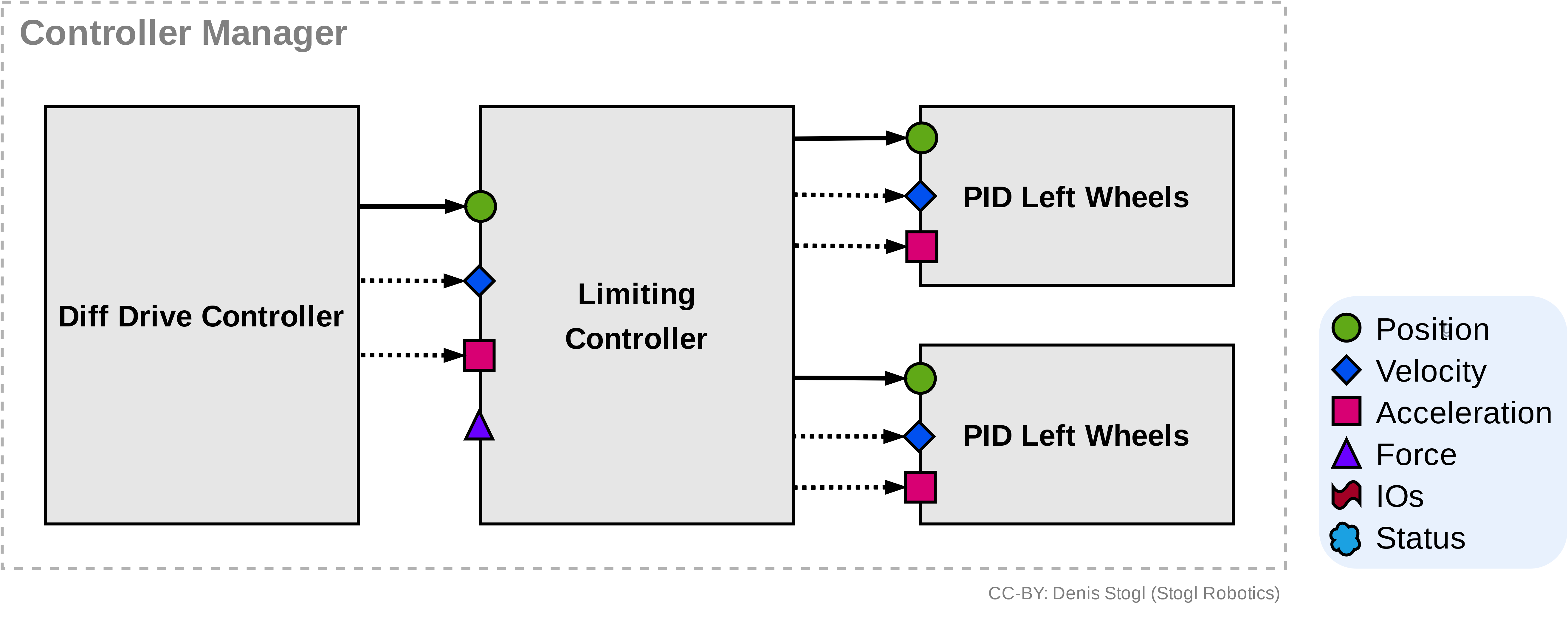
There are two types of controllers in ros2_control, "standard" and "chainable".
A chainable controller exports reference interfaces that enable other controllers to connect in front of them.
Branch: 9-chaining-controllers/task
Setup a chain of Joint Trajectory Controller and two pid controllers, one for each joint.
-
Create a
rrbot_chained_controllers.yamlconfiguration incontrolko_bringup/configfolder. -
Create a new launch file named
rrbot_chained_controllers.launch.pyin thecontrolko_bringuppackage. -
Start the launch file and investigate the controller's chain:
- Which CLI commands can you use for that?
- How are chained controllers integrated into ros2_control?
-
Switch controller to use the newly created chain instead of
forward_command_controller.
TIPP check the .yaml files with parameter description and example parameters in the src and test folders.
Branch: 9-chaining-controllers/solution
-
Check the newly created files listed above.
-
Use the following commands to introspect the system:
ros2 control list_controllersros2 control view_controller_chainsros2 control list_hardware_interfacesto see all interfaces in the ros2_control instance
-
Switch controller to use the newly create chain:
ros2 control switch_controllers --deactivate forward_position_controller --activate pid_controller_joint1 pid_controller_joint2 preceeding_forward_position_controller
The modular architecture of ros2_control where each hardware interface is a plugin that can be dynamically loaded, makes composition of hardware components very easy. Let's imagine a situation where a manipulator should be attached to a mobile robot. If there are drivers for those two components already available we can reuse them without changing a single line of code. Of course we will have to write a launch file, create URDF for the newly composed robot and adjust controllers for it.
The following figures are showing different architecture of hardware interfaces with monolithic or modular structures of it.
Attach the RRBot from controlko_description repository on top of the DiffBot from the ros2_control_demos repository.
-
Create a new URDF file that puts RRBot on top of DiffBot and create a
view_rrbot_on_diffbot.launch.pyin thecontrolko_descriptionpackage. -
Create the
rrbot_on_diffbot_controllers.yamlfile incontrolko_bringup/configwith the controller's configuration. -
Create a launch file
rrbot_on_diffbot.launch.pyin thecontrolko_bringuppackage that starts the ros2_control framework and both robots using the Mock System plugin. -
Configure Simulators to use the RRBot on DiffBot configuration.
- How many
*_ros2_controlplugins should be loaded? - How many
GazeboSystemplugins in<ros2_control>-tag should be defined?
- How many
TIPS: DiffBot can be visualized using:
ros2 launch diffbot_description view_robot.launch.py


